
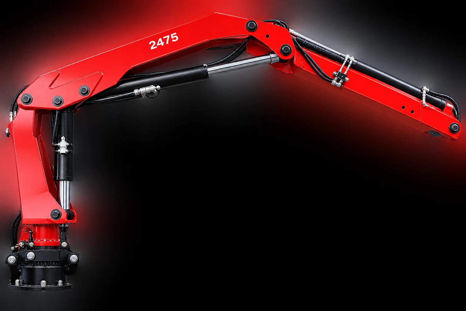
Truck-mounted lifting, engineered for the load.
Hydrolift knuckle-boom loader cranes — presented through the Al Furat partnership for commercial vehicle and fleet applications. From compact delivery handling to heavy-duty high-reach work across four models.
High-tensile steel. Hydraulic telescopic reach.
Hydrolift truck-mounted knuckle-boom cranes are built for commercial vehicle applications — delivery fleets, building-material handling and service operations. High-tensile steel construction and hydraulic telescopic booms support versatile material handling from a folded, chassis-mounted envelope. The range spans a compact 5.3 tm unit through to a heavy-duty family reaching 16 metres, all presented and supported through Al Furat.
- Four models — 675 K2, 1175 K2, 1675 and the 2475 (K1–K6) family
- Verified lifting data reproduced directly from the manufacturer brochures
- Configuration-dependent safety and control packages: Hx, HPS, HPro and HPro+
- Manufacturer cites EN 12999 for loader-crane design
Four cranes. Select a model.
Each model shows its product image, a concise introduction, verified headline specifications and — where published — the original manufacturer datasheet. Images are framed consistently but are not drawn to the same physical scale.
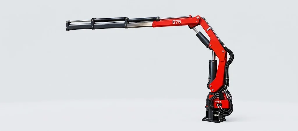
Hydrolift 675 K2
Compact truck-mounted lifting for delivery fleets, service operations and material handling. The lightest crane in the range, with a 7.2 m hydraulic reach from a 760 kg installed base crane.
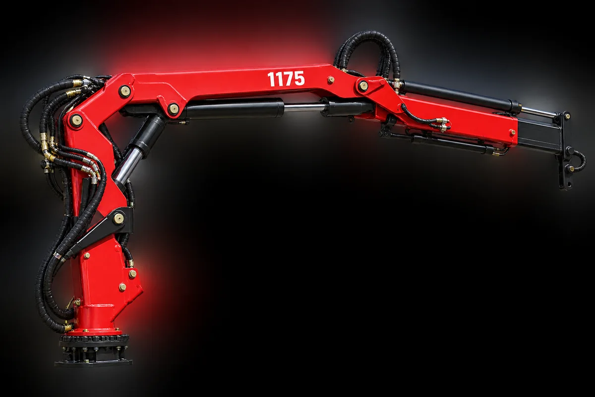
Hydrolift 1175 K2
A versatile loader crane for building-material deliveries and demanding fleet handling duties — nearly double the lifting moment of the 675, with a 7.6 m hydraulic reach.
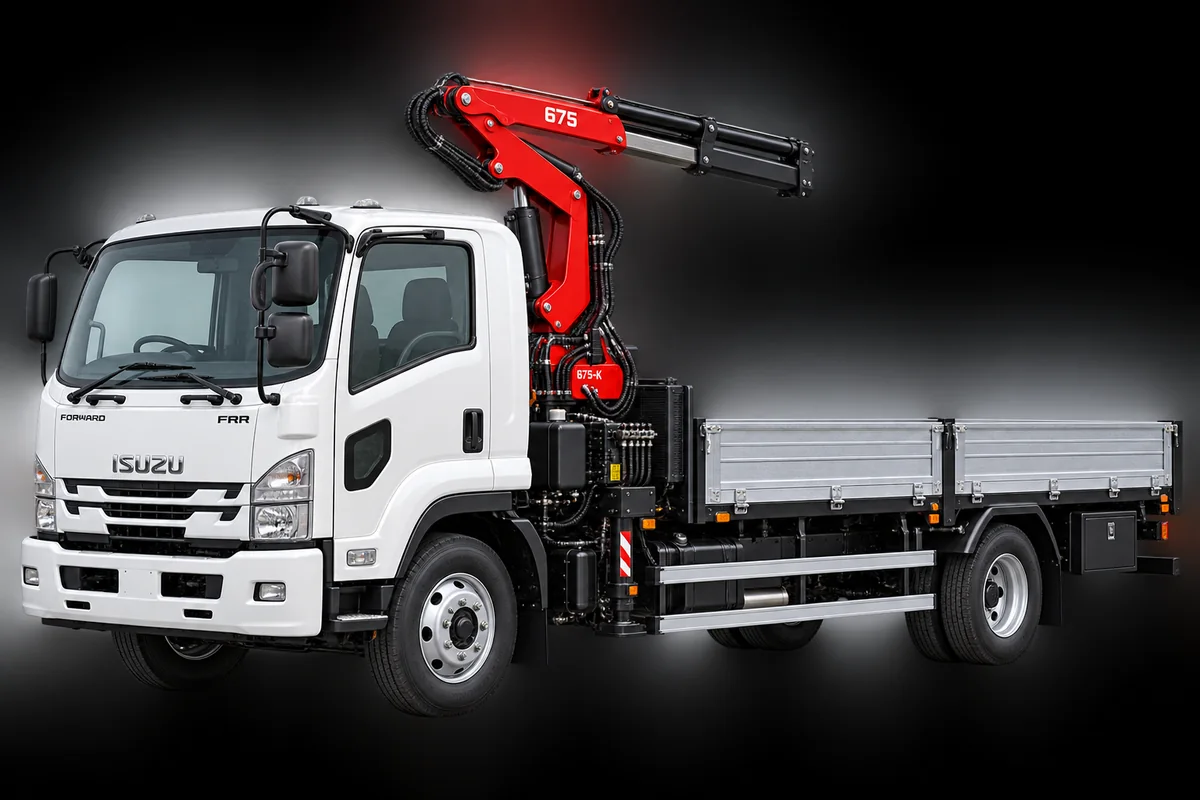
Hydrolift 1675
The 1675 sits in the Hydrolift knuckle-boom range between the 1175 and the heavy-duty 2475 family. A full manufacturer datasheet for this model was not supplied with this release, so we publish no lifting figures for it here rather than estimate them.
Verified lifting moment, load chart, reach and installation dimensions for the 1675 are confirmed directly with the Al Furat team on enquiry.
Image shown is a representative Hydrolift truck-mounted installation, for illustration of a mounted configuration.
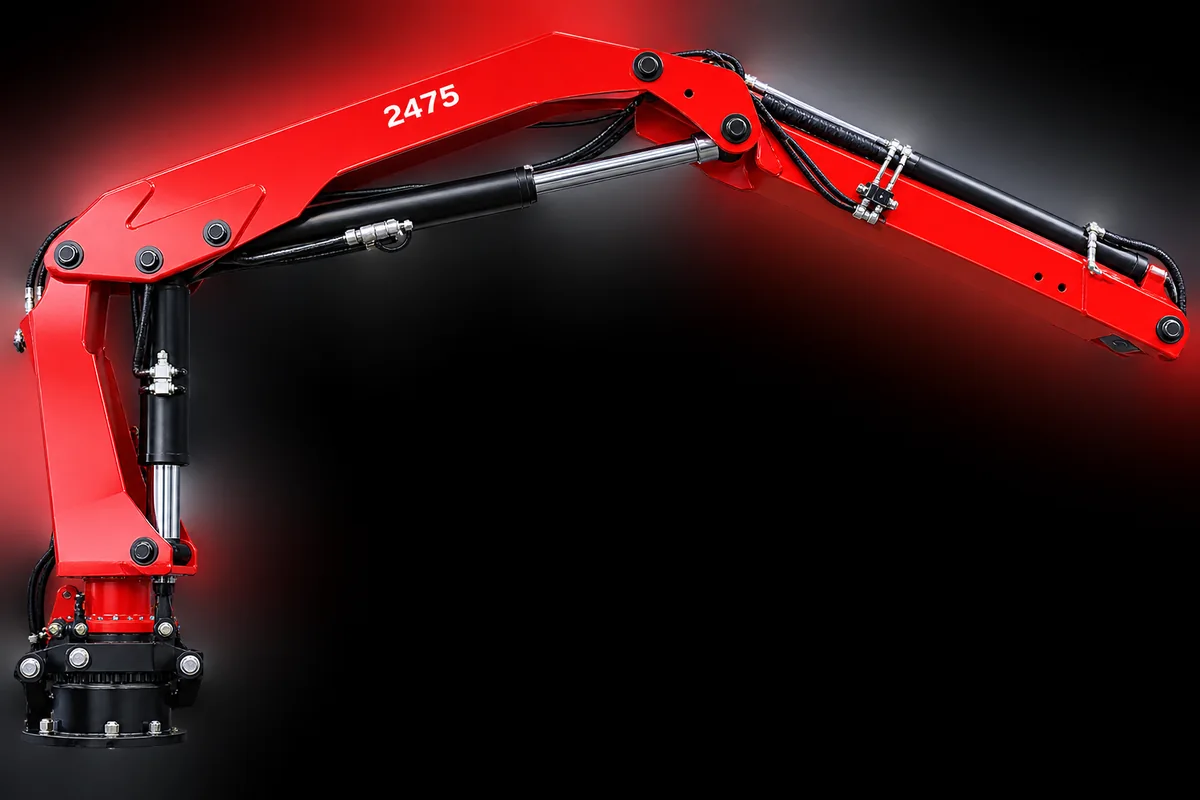
Hydrolift 2475 — K1 to K6
A heavy-duty loader crane family with six extension configurations (K1–K6). More telescopic extensions trade a little lifting moment for substantially more reach — from 6 m on the K1 to 16 m on the K6. Each configuration has its own load chart; figures are never mixed between them.
*Specification table states 300 bar; manufacturer feature text states 315 bar — confirm the ordered-variant value before installation.
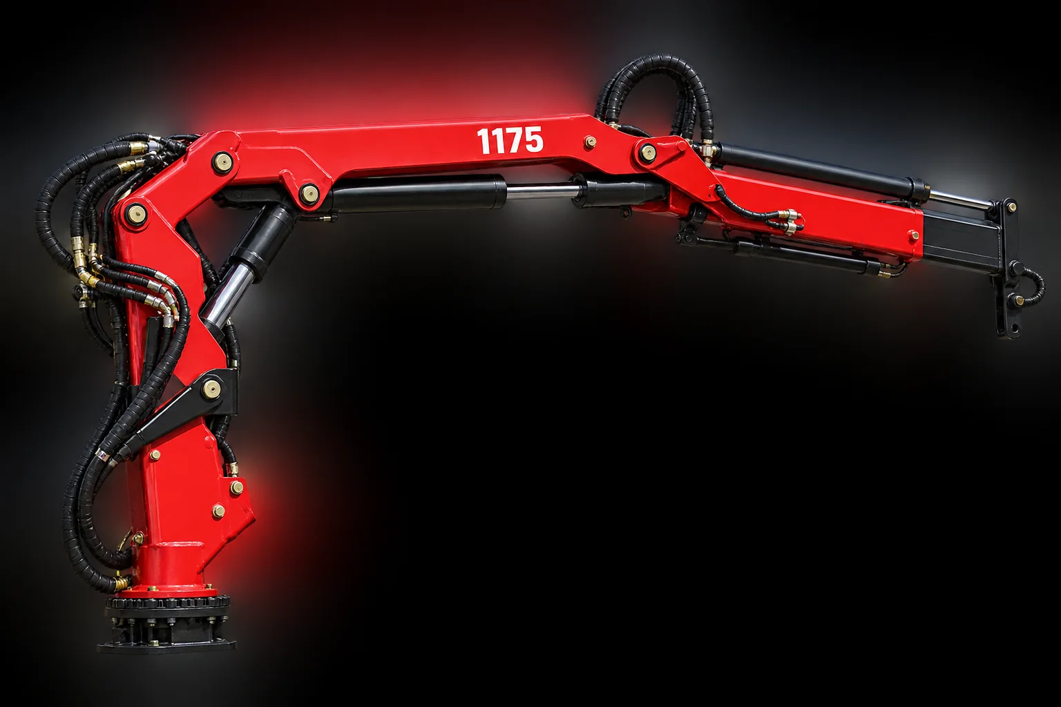
Anatomy of a knuckle-boom crane.
The knuckle (articulated) boom folds compactly behind the cab, then unfolds and telescopes out under hydraulic power. The callouts below identify the main assemblies common to the Hydrolift range — each supported by the manufacturer material.
 1
2
3
4
5
6
1
2
3
4
5
6
- 1
Base & slewing column
Mounts to the chassis sub-frame and rotates the crane. Slewing angle 400° across the range; slewing torque scales with model.
- 2
Lift (first-boom) cylinder
The hydraulic ram that raises the main boom. Working pressure runs from 240 bar on the 675 to 300 bar on the 2475.
- 3
Knuckle joint
The articulation between first and outer boom that lets the crane fold compactly and reach down below deck level.
- 4
Telescopic outer boom
Hydraulically extending sections set the reach — and, on the 2475, define the K1–K6 configurations from 6 m to 16 m.
- 5
Boom tip & attachment point
The lifting point at full extension, where rated capacity is quoted against radius on the load chart.
- 6
Hydraulic hose routing & high-tensile steel
Protected hose runs feed the cylinders; booms are fabricated from high-tensile steel for strength at low weight.
Callouts identify assemblies described in the manufacturer material. They are positioned on a representative studio image and are not a scaled engineering drawing.
Lifting performance, by the chart.
Select a model — and, for the 2475, an extension configuration — to see the manufacturer load points as a chart and a readable table. Capacity applies only at the stated radius and approved support configuration. Listed points are not interpolated ratings, and figures are never combined between configurations.
| Radius | Lifting capacity |
|---|
Where these cranes earn their keep.
The Hydrolift brochures position these cranes for commercial vehicle and fleet work. Three representative applications are shown below. Mounted-truck scenes are illustrative concepts of a configuration — not photographs of completed Al Furat projects.
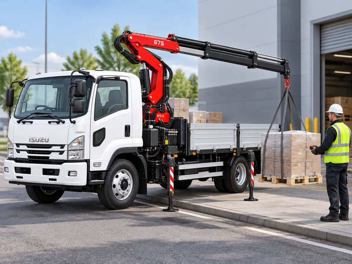
Self-loading deliveries — the crane unloads the bed onto the kerb or loading bay without a forklift or a second machine on site.
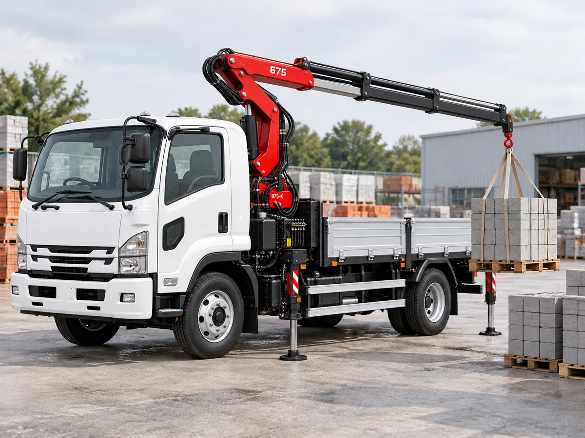
Positioned for building-material deliveries — palletised blocks, bagged goods and bundled materials lifted onto the kerb or across a site boundary.
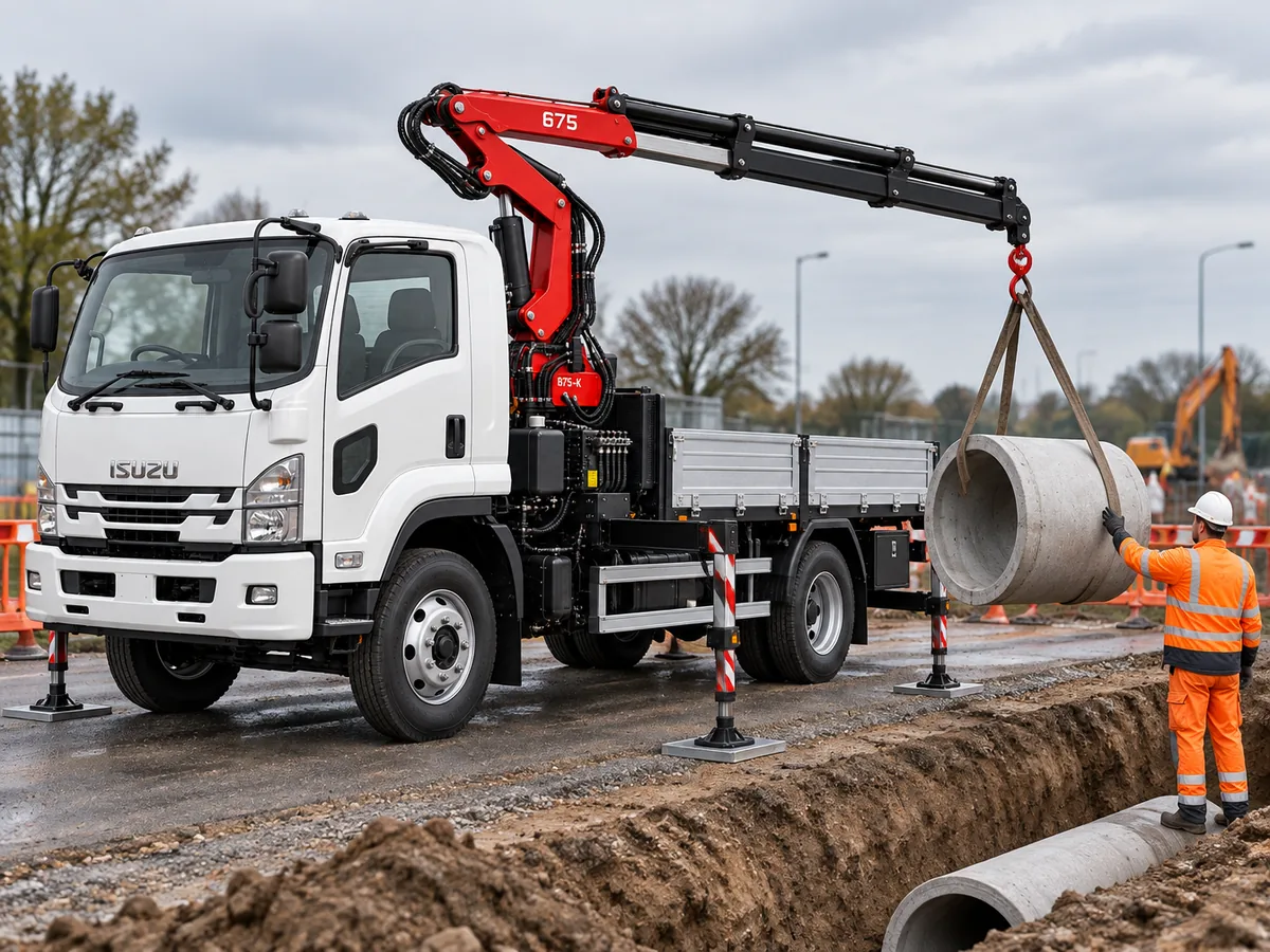
Placing precast sections, pipe and heavy components at roadside and utility sites — and, with the 2475 family, at high capacity and extended reach.
Operate only to the installed crane's load chart with the approved outrigger/stabiliser configuration. Imagery here does not depict rated loads or a specific site rigging plan.
Safety and control packages.
Safety and control equipment is configuration dependent across the range. Specify the required package when ordering — not every model includes every package by default.
Hx
The standard control package — baseline crane operation and control as supplied.
HPS
Overload protection — load-limiting safety that guards against operation beyond rated capacity.
HPro
Radio remote control — operate the crane at a distance for a clearer view of the load and landing zone.
HPro+
Safety, remote control and intelligent monitoring combined — the most comprehensive package in the range.
Stabiliser / outrigger spread
Stability comes from the outrigger (stabiliser) spread, quoted per model with a standard and an extra-long option. Capacity figures apply only at the approved support configuration.
- 675 K2 — standard 3,130 mm · extra-long 4,000 mm
- 1175 K2 — standard 3,900 mm · extra-long 4,800 mm
- 2475 — standard 5,100 mm
Standard vs. configuration-dependent
The Hx control package is the standard baseline. Overload protection (HPS), radio remote (HPro) and the combined safety/remote/monitoring package (HPro+) are configuration-dependent and specified at order. Stabiliser spread, extension count (2475 K1–K6) and mounting are confirmed per installation.
The range, side by side.
Headline figures across the range. For the 2475, the lifting-moment, reach and weight columns show the full K1–K6 span; the per-configuration load points live in the interactive chart above and the original datasheet.
| Specification | 675 K2 | 1175 K2 | 1675 | 2475 (K1–K6) |
|---|---|---|---|---|
| Lifting moment | 5.3 tm | 9.9 tm | On request | 20.1–22.2 tm |
| Hydraulic reach | 7.2 m | 7.6 m | On request | 6–16 m |
| Max capacity | 1,370 kg | 2,600 kg | On request | 8,900 kg |
| Max cap. at radius | 3.9 m | 3.8 m | — | 2.5 m (K1) |
| Slewing angle | 400° | 400° | On request | 400° |
| Slewing torque | 581 kg-m | 1,280 kg-m | On request | 2,800 kg-m |
| Standard weight | 760 kg | 1,440 kg | On request | 2,920–3,420 kg |
| Working pressure | 240 bar | 290 bar | On request | 300 bar* |
| Oil flow | 25 L/min | 40 L/min | On request | 60 L/min |
| Oil tank | 35 L | 100 L | On request | 160 L |
| Design standard | EN 12999 | EN 12999 | EN 12999 | EN 12999 |
Units: tm = tonne-metres (lifting moment); kg = kilograms; m = metres; bar = working hydraulic pressure; L = litres. *2475 pressure: table value 300 bar, feature text 315 bar — confirm ordered-variant value. Standard weight is the published crane figure; verify installed mass with options, mounting equipment and fluids.
Full technical specifications
Hydrolift 675 K2
5.3 tm · 7.2 m
| Lifting moment | 5.3 tm |
| Hydraulic reach | 7.2 m |
| Lifting capacity at 3.9 m | 1,370 kg |
| Lifting capacity at 5.3 m | 950 kg |
| Lifting capacity at 7.0 m | 710 kg |
| Slewing angle | 400° |
| Slewing torque | 581 kg-m |
| Folded height above chassis | 1,875 mm |
| Folded width | 585 mm |
| Folded length | 2,310 mm |
| Stabiliser spread — standard | 3,130 mm |
| Stabiliser spread — extra long | 4,000 mm |
| Standard weight | 760 kg |
| Working pressure | 240 bar |
| Oil flow | 25 L/min |
| Oil tank | 35 L |
Hydrolift 1175 K2
9.9 tm · 7.6 m
| Lifting moment | 9.9 tm |
| Hydraulic reach | 7.6 m |
| Lifting capacity at 3.8 m | 2,600 kg |
| Lifting capacity at 5.6 m | 1,660 kg |
| Lifting capacity at 7.4 m | 1,240 kg |
| Slewing angle | 400° |
| Slewing torque | 1,280 kg-m |
| Folded height above chassis | 2,021 mm |
| Folded width | 2,490 mm |
| Depth | 820 mm |
| Stabiliser spread — standard | 3,900 mm |
| Stabiliser spread — extra long | 4,800 mm |
| Standard weight | 1,440 kg |
| Working pressure | 290 bar |
| Oil flow | 40 L/min |
| Oil tank | 100 L |
Hydrolift 1675
Datasheet on request
No manufacturer datasheet was supplied for the 1675 with this release. Rather than estimate or borrow figures from another model, we publish no lifting data for it here. Verified specifications are confirmed with the Al Furat team on enquiry.
Request 1675 specifications →Hydrolift 2475 — K1 to K6
20.1–22.2 tm · 6–16 m
Per-configuration headline figures. Lifting capacities at each radius are shown in the interactive load chart above and in the original datasheet.
| Variant | K1 | K2 | K3 | K4 | K5 | K6 |
|---|---|---|---|---|---|---|
| Lifting moment (tm) | 22.2 | 21.7 | 21.2 | 20.8 | 20.5 | 20.1 |
| Hydraulic reach (m) | 6.0 | 8.0 | 10.0 | 12.0 | 14.0 | 16.0 |
| Standard weight (kg) | 2,920 | 3,080 | 3,200 | 3,330 | 3,420 | 3,420 |
| Slewing angle | 400° |
| Slewing torque | 2,800 kg-m |
| Folded height above chassis | 2,305 mm |
| Folded width | 1,152 mm |
| Stabiliser spread — standard | 5,100 mm |
| Working pressure (table value) | 300 bar |
| Oil flow | 60 L/min |
| Oil tank | 160 L |
Original datasheets
The 1675 has no published datasheet in this release — request its technical data through the enquiry form. All figures on this page are reproduced from the Hydrolift manufacturer brochures; specification values may change without notice.
Request a quote or technical data.
Tell us the model you are considering and the work it has to do. An Al Furat specialist will confirm the right Hydrolift configuration, lifting data and mounting for your chassis.
- Pick a model above, or ask us to recommend one for your duty cycle.
- For the 1675, request the verified datasheet and load chart.
- For the 2475, confirm the K1–K6 extension configuration.
- Control package — Hx, HPS, HPro or HPro+ — specified at order.